Meeting Building Codes for Structural Heavy Timber Frames
Vermont Timber Works designs and engineers all of the structural heavy timber frames and structural roof trusses that come through the office. For the design of the trusses, projects range from 16-foot king post trusses to 60 foot double chorded inverted trusses. Timber frame projects range from simple barns and saltboxes to 60-foot octagons.
The engineering department is responsible for the design of all of these structures. As a minimum, they ensure that the state building code is being met. The loads for the building are calculated for each project based on the occupancy, use, and location of the structure. The loads that are considered are the self-weight of the timber, dead, live, snow (balanced, unbalanced and drifting), and depending the on location, either wind or earthquake. The safety of the occupants and the performance of your custom designed building is always the design team’s priority.
When it comes to connecting the pieces of the timber frame together, Vermont Timber Works uses either traditional joinery or steel connection plates. The decision to use either method comes from the direction given to us by the client. Some people enjoy the look of the steel plates against the wood, while others prefer a more classic look to their timber frame. A combination of wood and steel joinery may be required to transfer the forces at the joint. This steel is typically concealed in the wood in this type of situation.
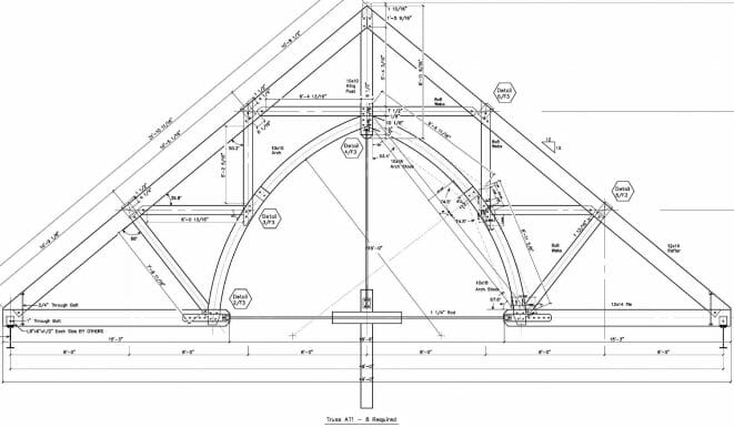
After the frame is engineered, shop drawings including bent elevations, plans, isometric views, and joint detail are created. We can provide stamped drawings and calculations as required by the local building officials.
Matthew McGinnis, P.E., is a Structural Engineer specializing in heavy timber and hybrid steel–timber structures, with nine years of progressive experience at Vermont Timber Works. He has engineered more than 175 heavy timber structures across 27 states, combining advanced technical expertise with hands-on shop and field experience. His strengths include connection design, FEA and CAD modeling, code compliance, and full-cycle project delivery.
The Concept
The first step is to get a basic concept going for the project. At this point, we are looking for any drawings that you may have on the project. If there aren’t drawings yet we will need, at the minimum, the overall size of the timber frame, desired spacing of the trusses or bent frames, the roof slope, the location of the project, and most importantly the owners aesthetic and design desires.
3D Preliminary Design
With this information, we can put together a preliminary design in our 3D drafting program CadWork. At this point, if we created the frame, we will send out a 3D PDF for review and concept approval. If we are working from existing drawings or approved preliminary drawings, the model is exported into RISA 3D for engineering design.
Design Loads & External Forces
In RISA the design loads and load cases are applied to the structure in 3D. These loads are calculated based on the location of the structure and the local governing building codes. The loads include self-weight, dead, live, snow (balanced, unbalanced, and drifting), and wind or earthquake loads. Using the design program, the timbers are sized. Additional information that is obtained from the program is the forces that need to be transferred when the connections are designed. When sizing the timbers these forces are also considered so that there is enough material to make a connection in timber using traditional joinery.
Engineering the Joinery
Once the timber is sized and the joint forces are obtained, the CadWork model is updated and the design of the joinery begins. The design of the connections is a critical part of the design. Several factors need to be considered when designing the connections or joints. The most obvious design factor is the forces from the loading at the joint. Each joint, whether it is wood, steel or a combination of the two, is analyzed for compression, tension, shear, etc. and is designed to transfer the forces from one member to the next. Another factor, that needs to be considered, is the performance of the joint over the life of the building as it is loaded and unloaded. Wood is a natural material and it will shrink, check, and creep over time. It is also important that the joints be visually appealing. Timber frames and trusses are typically left exposed so you will see the joints for the life of the structure. There are many different types of joints that can be used to create the connections. You can see examples of types of connections in the joinery section of this website.
Exporting 3D Models to Create Shop Drawings
Upon completion of the joinery, design, and drawings in 3D, shop drawings are ready to be produced. The 3D model is exported to create the shop drawings. So a complete design package can be put together from conceptual drawings, through design engineering, through the design of joinery, to the completed shop drawings with an engineer’s stamp.
FAQs About Timber Frame Engineering