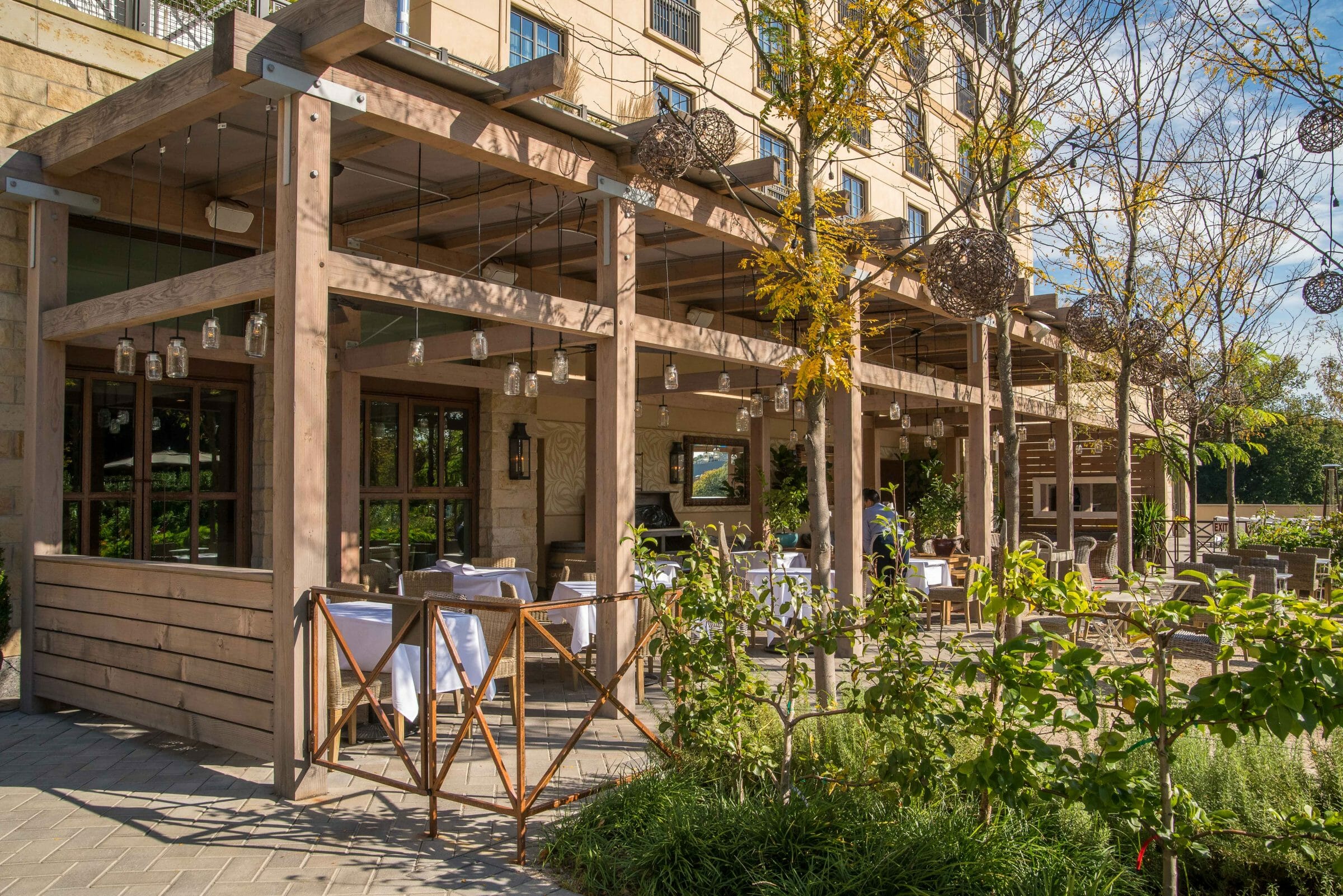
How are timber frames designed to resisit lateral loads from wind, seismic and unbalanced snow?
Lateral loads, which are loads from wind, unbalanced snow and seismic activity, can be resolved in timber frame design by using wood bracing, normally in “compression only” joints, but sometimes the braces are engaged in both compression and tension by embedding steel tie rods in the brace.
Often, architects prefer to use short braces, or no braces at all. In those cases, the lateral loads must be resolved in the wall and roof systems like in a conventionally stick framed buildings. A positive fastening system needs to still be designed between the wall system and the timber frame and then connected to the foundation. With good fastening between the walls and the posts, uplift from the lateral loads can be transferred through the posts bases into the foundation.
When window walls are part of the design, resolving the lateral loads gets trickier. Glass necessitates designing for very small deflections to prevent the glass from cracking or the seals on multi-pane windows from cracking and clouding. Large braces can be placed in front of the windows, usually with hidden or exposed steel tie rods, to resolved the lateral loads, or a steel moment frame can be built within the wall outside of the frame to resolve the loads. Perpendicular wind loads are also a concern when building window walls. Timber or steel columns can be installed to take care of deflection in the plane of the window wall.
Another way to resolve lateral loads is to use X-Braced diagonal tie rods between the timber columns. The x-bracing is a very contemporary look. some designers love it, and others prefer a more traditional solution.
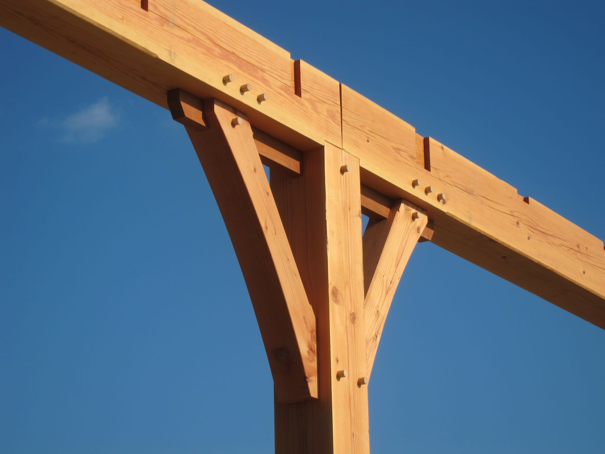
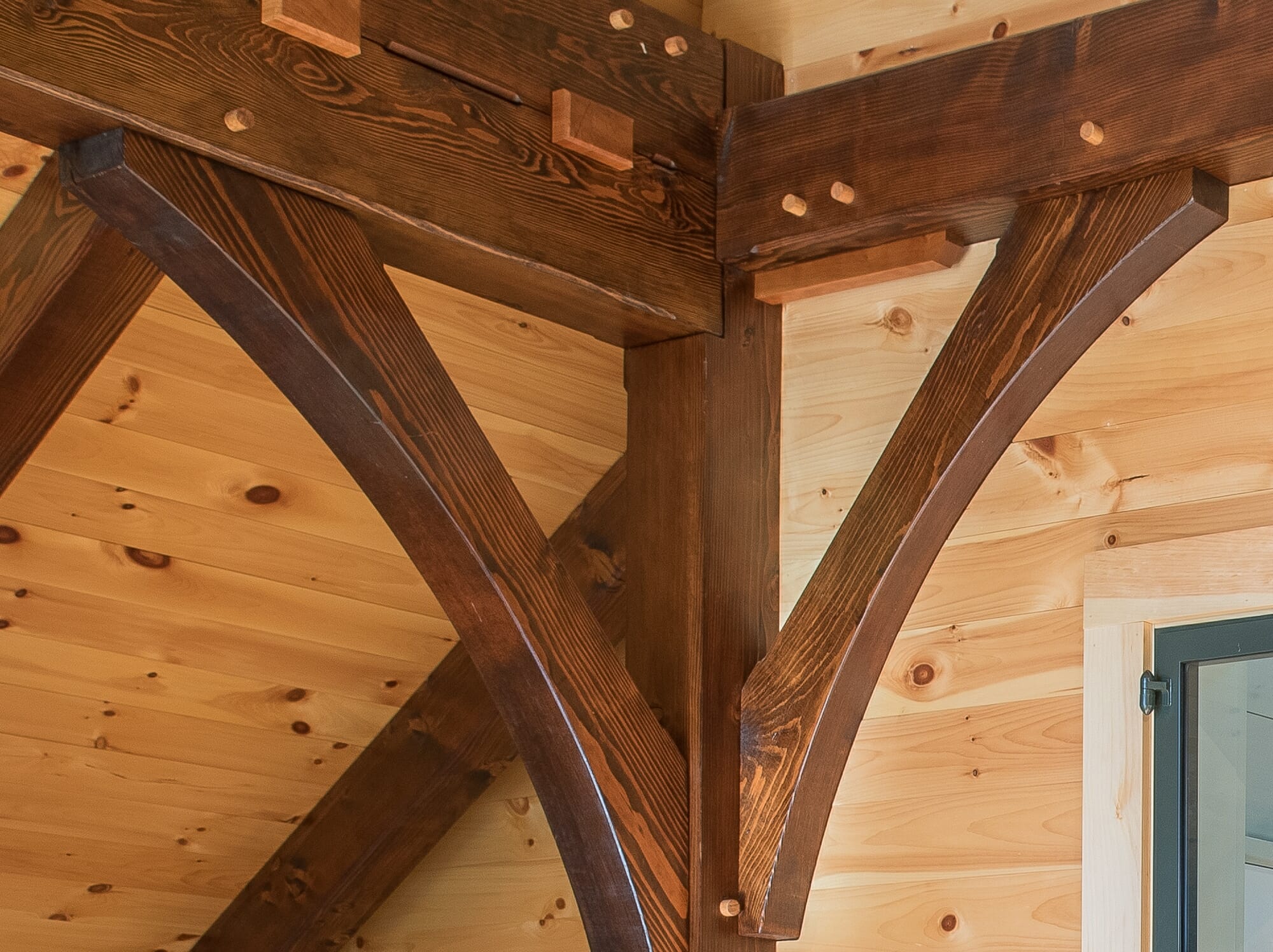
When a clean timber look without braces is the goal, steel tee channels can be embedded between the timber column and the horizontal girt above to create a moment connection (see photo below).
See our blog “How Do Timber Frames Resolve Lateral Loads” for more detailed information.
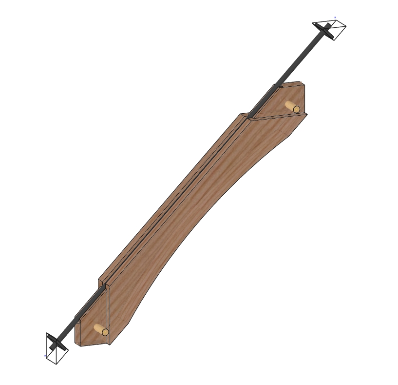
Timber brace with hidden steel tie rod.
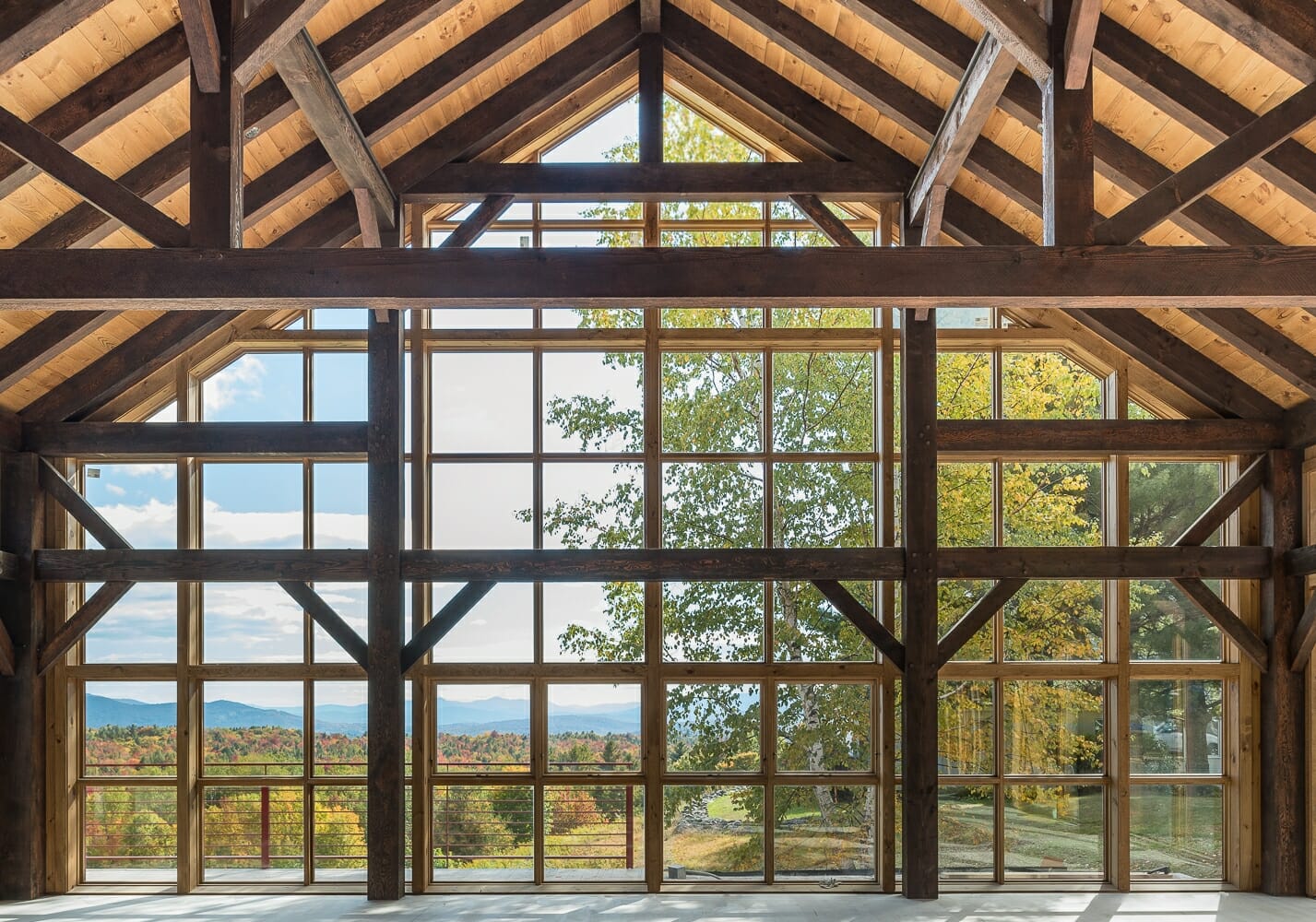
Timber Framed Window Wall
Timber and steel moment connection,
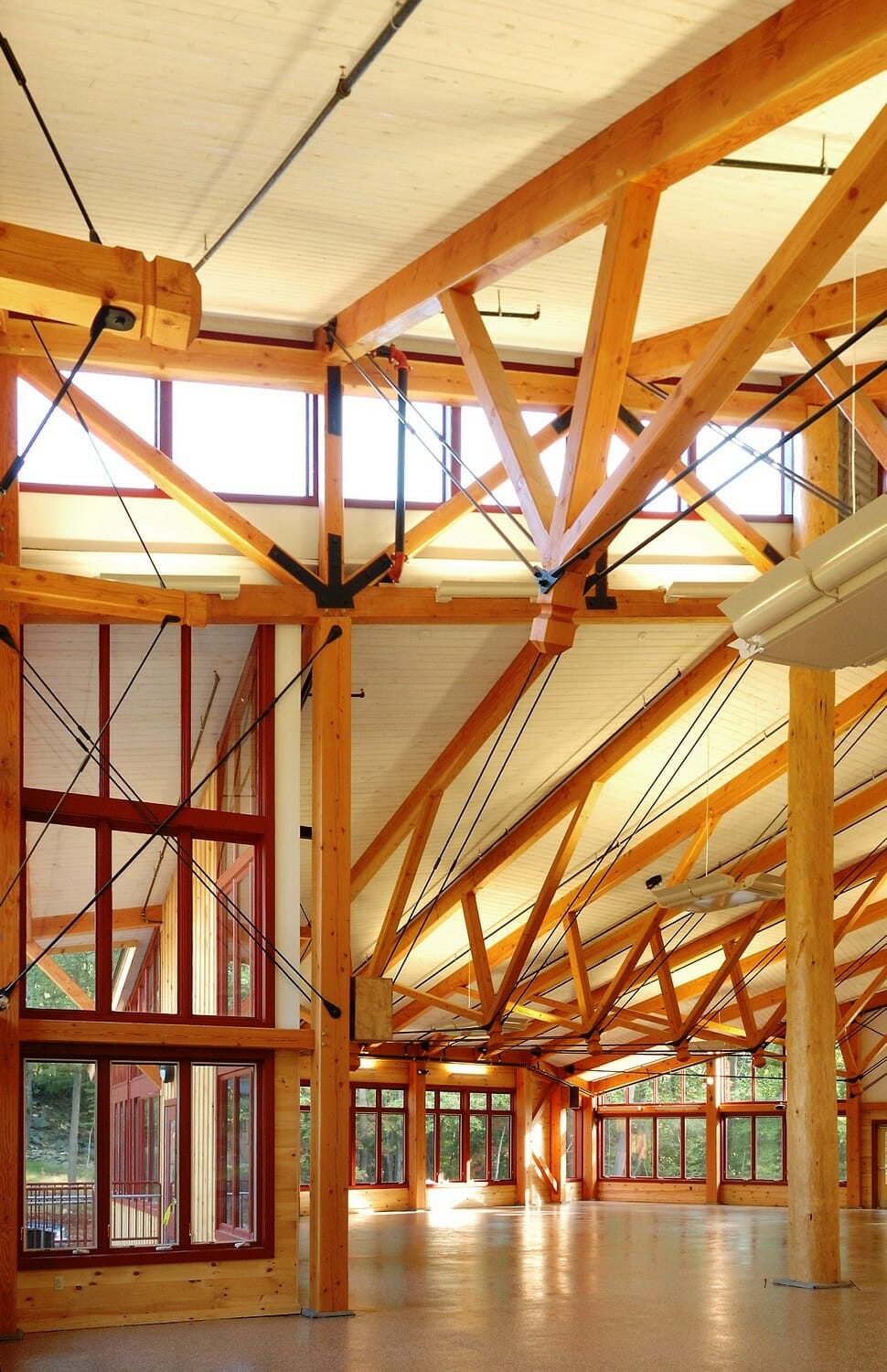
Steel Rod X-Bracing
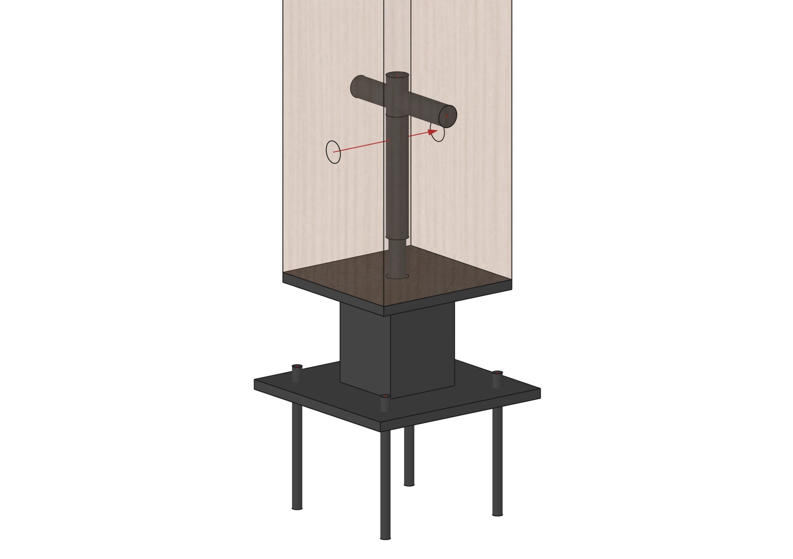
Can lateral loads in a timber frame be resolved in the post bases?
Yes, one way to resolve lateral loads in a timber frame is to create a moment connection at the bottom of the timber columns. that can be done with a secure base plate bolted and epoxied down to concrete and a knife plate that extends up into the post.
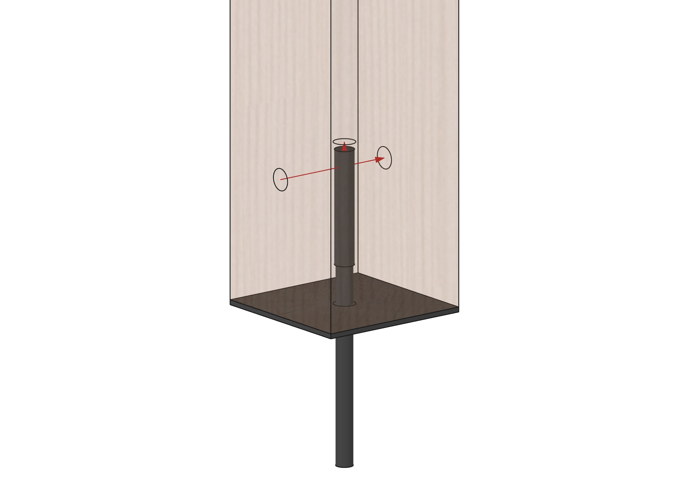
Other post bases include timber-linx, stand-offs and simple rods, but they don’t resolve lateral loads on their own. They can resolve uplift from shear walls however.
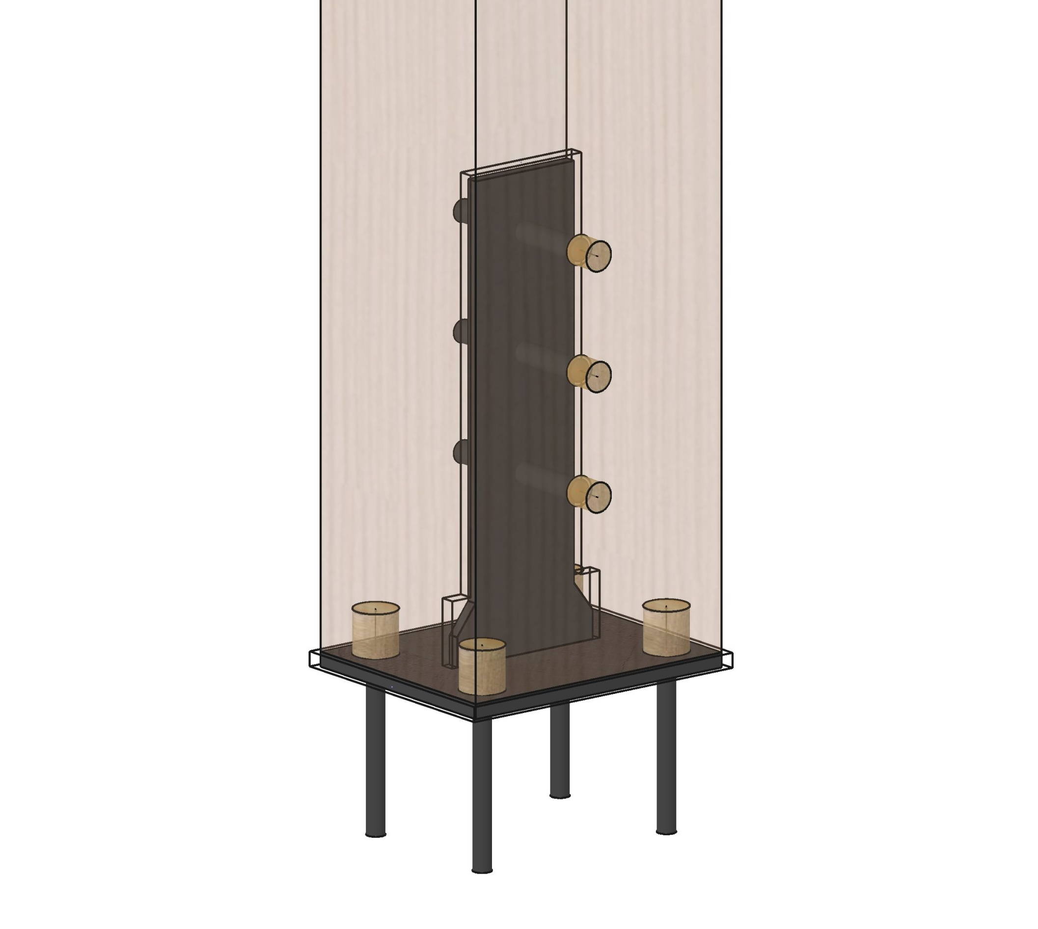
Timber post moment base with knife plate.
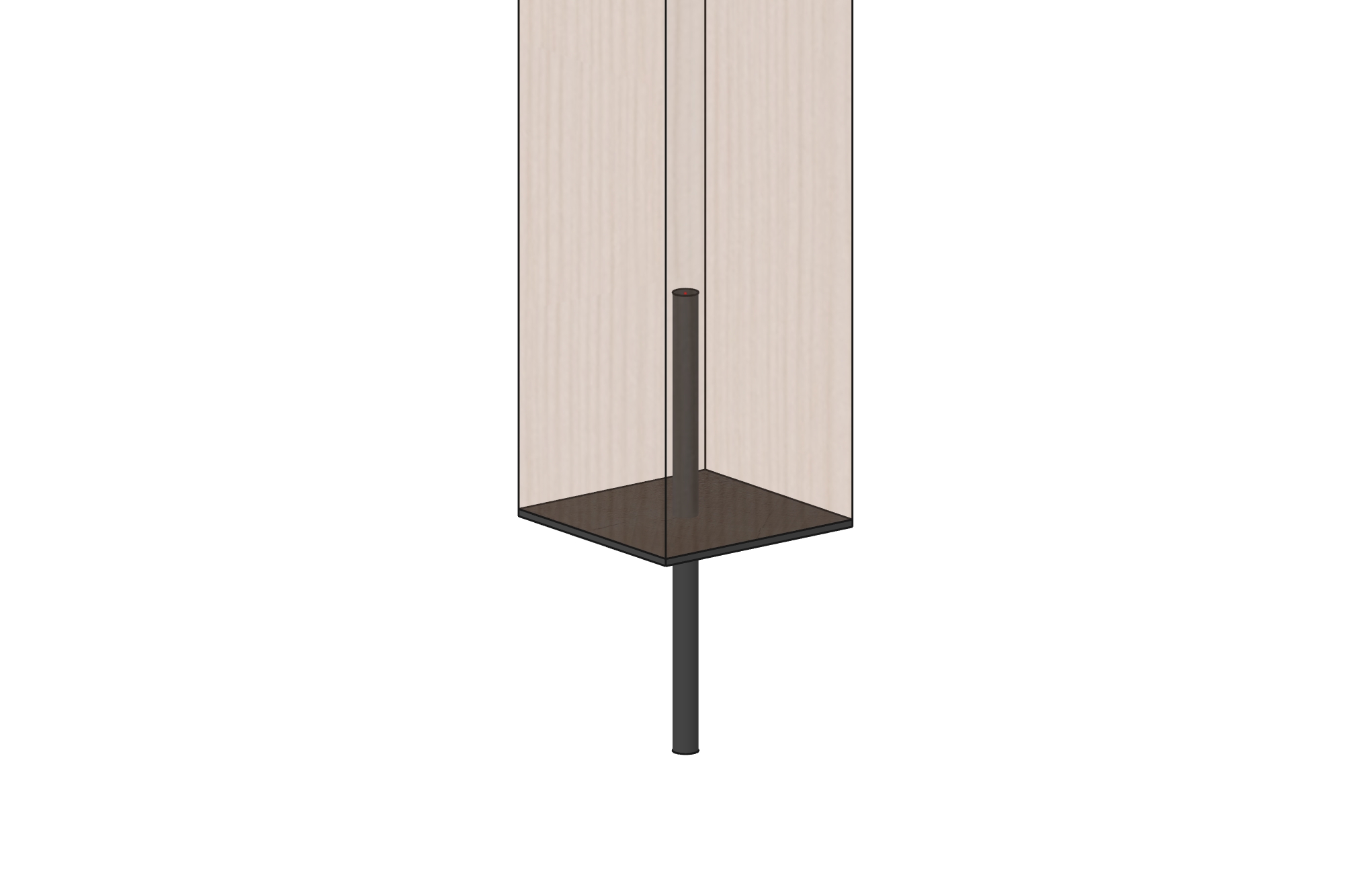
Post base with rod & plate.
Post base with stand off and timber linx
Post base with rod and timber linx.
Does peg size matter when designing a timber frame?
Yes, peg size does matter when designing a timber frame. This can be illustrated when thinking about the area of a circle, i.e. how the diameter of a peg relates to the peg’s cross sectional area and therefore its ability to resist bending and failing. Π*R Squared is the formula for area. The formula for a 3/4″ peg is 3.14*0.75/2*0.75/2= 0.44″sq . Whereas the formula for a 1″ peg is 3.14*1/2*1/2= 0.78″sq – almost double the size with just 1/4″ more in diameter. An 1 1/4″ peg has an area of 1.23″sq. , a 63% increase in area, and therefore strength, over a 1″ peg.
There is a caveat though; the larger the peg size, the more “relish” or distance behind the peg is required to achieve the full design load. the NDS (National design standard for wood construction) requires seven times the diameter of the peg for full value. I.e. 5.25 inches is required for a 3/4″ peg, 7″ is required for a 1″ peg and 8.75″ is required for a 1 1/4″ peg. That is a lot of relish and reductions can be taken. Joe Miller of Fire tower Engineering did quite a bit of research on this topic and wrote an article in the Journal of Structural Engineering on peg design finding that multiples of diameter is not as important as shear strength behind the peg. We engineer our pegs based on his work.
At Vermont Timber Works, we start with 1″ pegs and use them for most of our joints connecting braces, girts and connectors together. When a pegged look is desired, but space is tight, like when designing brackets, we will go to 3/4″ pegs in order to pin the connection when the loads are small. We will use to 1 1/4″ pegs in tension members like through tenons in king posts and ties. Occasionally we will even use 1 1/2″ pegs when tension loads are high because of their increased capacity. Using 1 1/2″ pegs or bigger is tricky though because pegs of that diameter don’t flex when they are driven. They can actually split the timbers if they are not driven very carefully. In those cases, we do not use draw bore holes (holes that are slightly off set to “draw” one timber closer to the other as the peg is driven). We will pull the timbers tight with come-a-longs and drill the peg holes in the joints on site to assure that the pegs can be driven cleanly.
Spacing of pegs is also important. In tension connections the NDS requires 7d (diameters of the peg) distance from the end of the timber for pegs loaded parallel to the grain, and 4d for compression members. The pegs should be spaced no closer than 4d, 5d is better, to prevent the timber from splitting between the pegs. Edge distances are 3d for full design value. Reductions are possible, but need to be calculated using the formulas in the NDS.
What are Unbalanced Snow Loads?
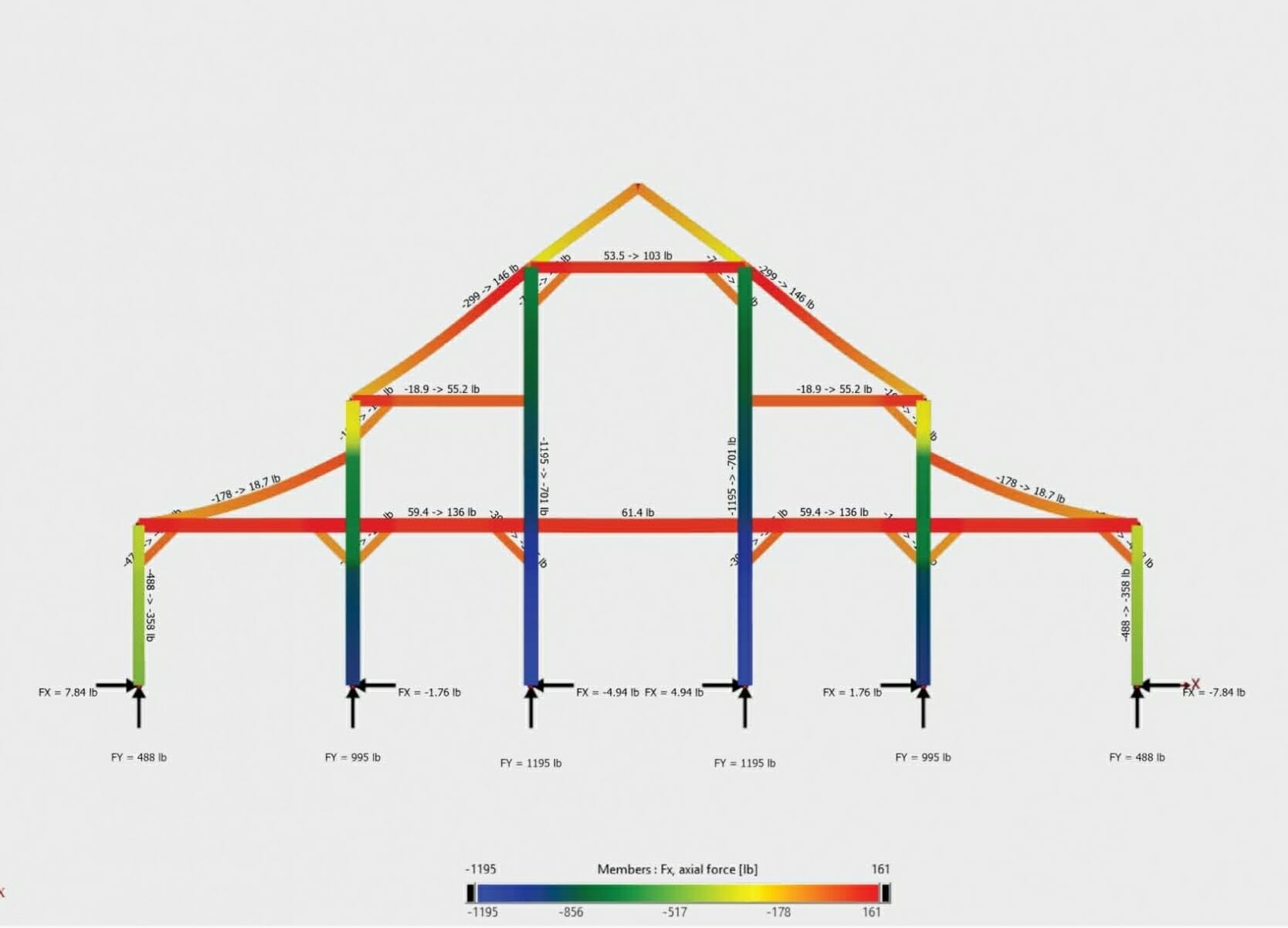
When designing timber frames in areas where it snows, not only do we need to think about the weight of the snow on the roof and how to hold it up, we also need to think about what happens when snow drifts and blows to the other side of the roof – how does that affect the forces on a structure? Does the extra weight on one side tend to push the structure over? How do we resist a force when it is unbalanced? What happens on sunny days when the sun melts the snow off of the top of the roof only for it to drip down and re-freeze on the lower half of the roof as heavier blocks of ice? Then what happens when more snow piles up on the roof during a storm in the night and the melting and refreezing happens again the next day? Does enough snow and ice accumulate to make the structure, or part of the structure fail? Then what happens when the wind blows and starts trying to push the structure over? All those are examples of “unbalanced” snow loads and all have to be engineered for.
At Vermont Timber Works, we think about all the forces on every timber frame we design and engineer solutions for every possible condition. Resolving unbalanced forces includes using bigger beams for the higher gravity loads, adding additional bracing to counteract a building’s tendency to lean under load and checking the foundation to make sure that the unbalanced loads can be resolved down to the ground.
Can a timber frame use only traditional wood peg joinery and still meet today's building codes?
Yes, but it is tricky and requires a lot of math. Building codes today have gotten much stricter than years ago, and for good reason. As time goes on, we humans record and study buildings that fail structurally due to wind, snow, hurricanes and earthquakes. Every few years the national design standard and international building code is revised to try to mitigate building failures and make buildings more resilient to the natural forces that act upon them. With timber framing, an easy way to strengthen a building is to hide steel rods and plates within the timber. Most of the time the hidden steel never sees any load, but during significant natural events, like huge snow storms and hurricanes the steel engages with the timbers and keeps the occupants safe inside. Steel reinforcing is not a dirty word in timber framing. Timber framing evolved from ship building and ship builders since the Romans have used iron connections to add strength to the timbers.
We do have clients who are traditionalists and love the story of timber frames that are built with dovetails and pegs without any steel reinforcing and still can withstand the natural forces that act upon them. For those clients, we get our calculators and computers out, sharpen our pencils and design joinery that can meet today’s most stringent building codes. We use longer tenons with more “relish” behind the pegs, wedges to pull the dovetails tight and long splines to connect one timber to the next. Sometimes the spans need to be shorter and the timbers need to be closer together, but we can make it work.
Traditional timber joinery with a cherry spline.
Timber joinery with pegs, splines and keys.
Dovetail joint in a timber frame.
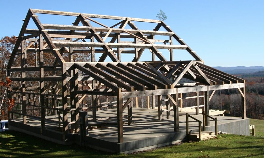
Traditionally joined timber frame barn.
How is tension resolved between framing members in a timber framed building?
Compression is easy to resolve in wood to wood connections, tension is is more of a challenge. The first step is trying to release the tension in as many joints as possible while designing in RISA or Visual Analysis, but the tension will eventually find a load path through the frame. If the loads are light at particular location, <1 kip, we can usually get the tension resolved in a standard mortise and tenon joint with a peg or two. When the tension is over 1.5 kips but less than 5 kips, we can use longer longer tenons with more “relish” behind them and larger diameter pegs.
Once the tension exceeds 5 kips (and sometimes before) we need to start thinking about embedding structural steel grade 50 rods with bearing plates into the frame. If the tension exceeds 10 kips, we look at using bolted steel side plates with embedded shear plates. Each shear plate will resolve around 4 kips, so we can design for tension loads of 60 kips or more.
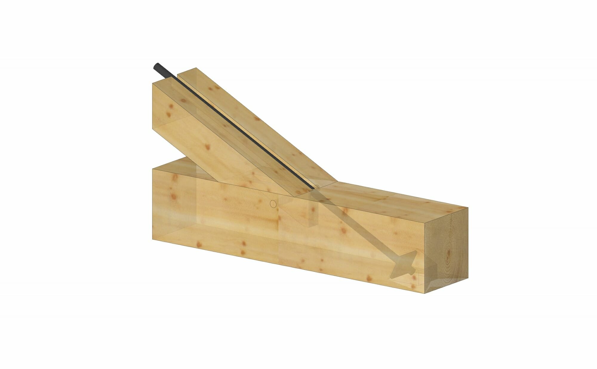
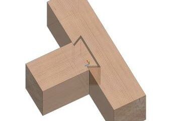
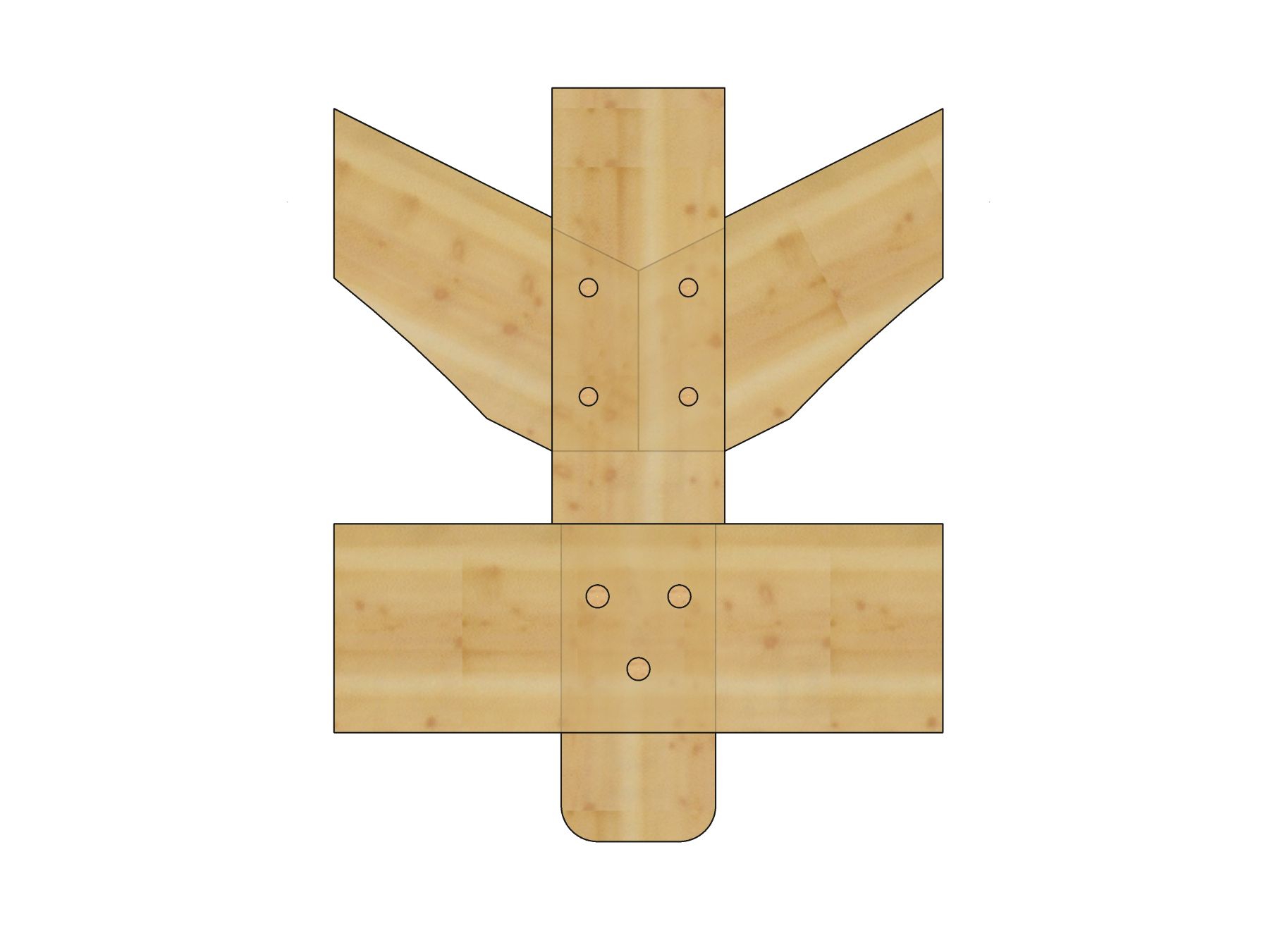
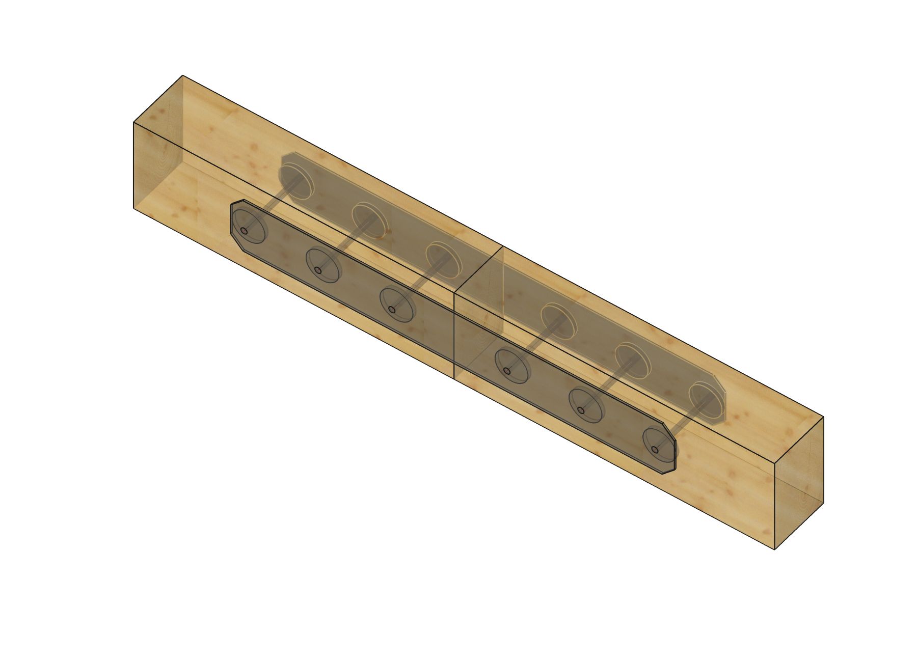
A hidden steel tension rod in a heavy timber connection. 10-15 kips or more of tension can be resolved with this joint.
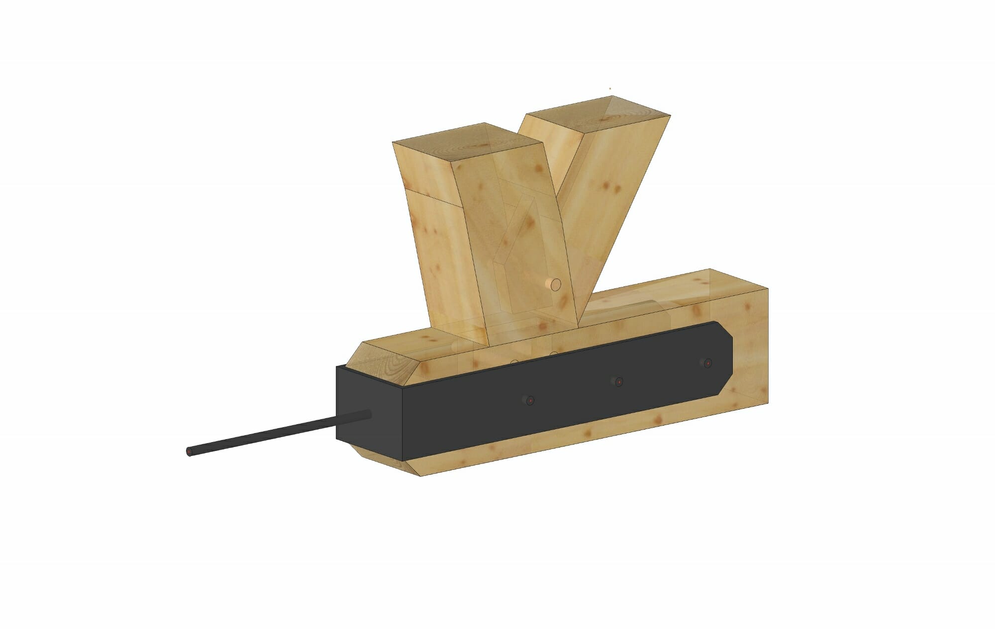
A through tenon connection between a king post and a tie. Several thousand pounds of tension can be resisted with this joint.
Steel gusset plates with shear plates. Each shear plate can develop about 4k of tension or compression capacity, so this joint can resolve 24k or more of tension.
A steel tension rod can be added in a bottom chord to open up the frame visually. This connection can develop 32 kips of tension or more.